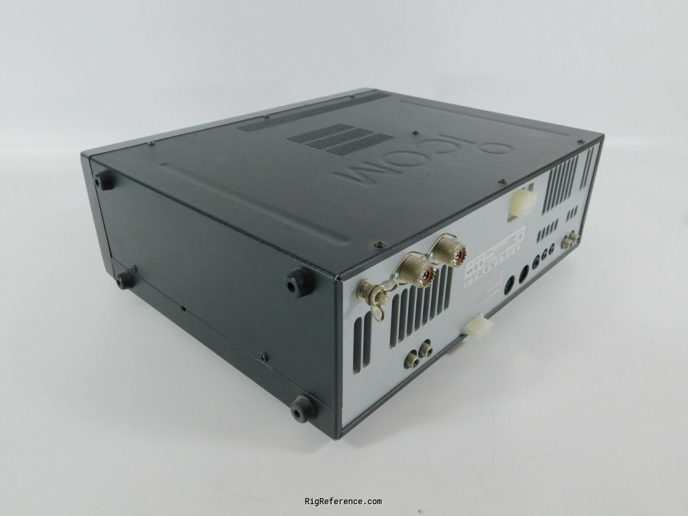

- #Icom ic 756 pro ii manual pdf#
- #Icom ic 756 pro ii manual mods#
- #Icom ic 756 pro ii manual software#
NOTE: The previous two photos depict an extreme and rare example. While he was transmitting from his other station, his wife alerted him to smoke coming from his ICPRO in another room.

NOTE: The following two photos depict an extreme and rare example. The pictures below show a worst-case scenario. The collector voltage should be around If left unchecked, the situation may deteriorate until the damaged SMD components overheat and become charred, possibly damaging the circuit-board. The base voltage should be 0-volts RX, and 0. This test works because the attenuator interrupts the path of oscillation. The symptoms can be one or more of the following. This will not affect the 2-meter band on the series. But many times, the only noticeable issue is the transmitter will tend to oscillate intermittently on the higher HF bands 6, 10, or 12 meters. Important Note: Although I have first-hand knowledge of the damaged circuitry and the necessary repairs, I only have second-hand knowledge as to the cause of damage, which was acquired by interviewing customers about their station setups and operating practices. You should be aware of the fact that transmitter is set to transmitt on amateur bands only band-pass filtersso transmitting outside of those frequencies have to be with limited power only, or you can easily demage the transmitter!Sometimes, components on the RF Unit may also be affected. Of course, transmitting outside the amateur frequencies are not allowed neither for licenced radio amateurs! It will restart automatically and voila! The transmitter is "unloicked" now, and will be able to transmitt on all frequencies from about 0. After you have removed diodes as shown on above pictures, return the DSP-module, return the botom cover into its place and turn on the transceiver. Nonton film indonesiaĬarefully using a magnifying glass you should remove the diodes located at the PCB as shown on the picture below. Carefully unplug DSP-unit and place it aside. There is DSP-unit plug in metal box on the right side. Place the transceiver on the table with face toward you, upside down. This modification allows transmitter to transmit on whole frequency range. Transmitter is factory limited to transmit on amateurs bands only.

Enjoy.It can receive from 30 kHz up to 60 MHz continuously and transmit all mode, all bands with watts RF power output. Now IC-756PRO2 will transmit from 100 kHz to 60 MHz without any gaps!!! Dunno about RF power on 136 kHz, could be it possible, anyway be carefully with transmitting lower than 1.8 MHz.

Icom IC-756 PRO II (IC 756 PRO II IC756PROII) technical specifications Icom IC-756 PRO II (IC 756 PRO II IC756PROII) technical specifications :
#Icom ic 756 pro ii manual mods#
Icom IC-756 PRO II (IC 756 PRO II IC756PROII) TX mods 100 Khz - 60 MHz Icom IC-756 PRO II (IC 756 PRO II IC756PROII) TX expand on IC 756PROII #23 EU models Icom IC-756 PRO II (IC 756 PRO II IC756PROII) 6M oscillation problem Mods for Icom IC-756 PRO II (IC 756 PRO II IC756PROII) : Schematics for Icom IC-756 PRO II (IC 756 PRO II IC756PROII) :
#Icom ic 756 pro ii manual pdf#
PDF Adjusments Procedures Manual with schematics for Icom IC-756 PRO II (IC 756 PRO II IC756PROII) : PDF User Manual for Icom IC-756 PRO II (IC 756 PRO II IC756PROII) : Icom IC-756 PRO II Instruction Manual
#Icom ic 756 pro ii manual software#
Programming software for Icom IC-756 PRO II (IC 756 PRO II IC756PROII) : Programming interface schematics for Icom: Icom IC-756 PRO II (IC 756 PRO II IC756PROII)


 0 kommentar(er)
